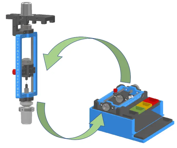
VHR System
The Totems VHR (Vertical Horizontal Rotary) fixturing system is designed for the individual positioning and inspection of small 2D or rotational parts on measuring devices equipped or not with a rotary unit. The main goal is to maximize part visibility throughout the entire inspection cycle, ensure ergonomic handling, and enable smooth part transitions.
Usage
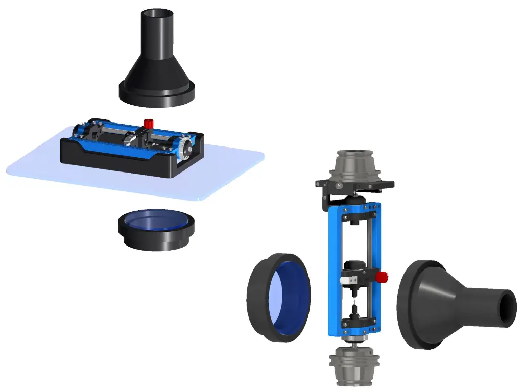
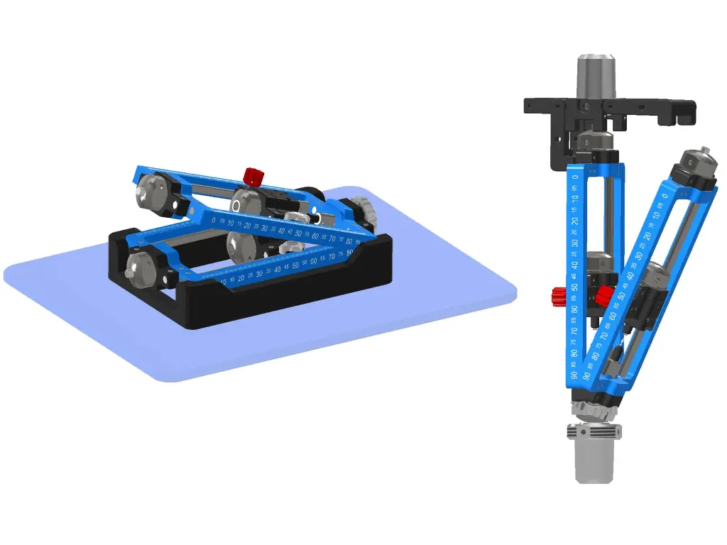
Vertical or horizontal layout
Depending on the type of measuring equipment used, the fixtures can be set up in either vertical or horizontal orientation.
Mounting and coupling
Mounting and coupling to the rotary unit of the inspection machine is achieved via simple lateral or vertical insertion, with magnetic contact-based coupling.
It is also possible to manually rotate the part holders if the inspection device does not have a motorized rotary unit.
Optimized inspection workflow
The inspection flow is optimized for greater efficiency. With racks featuring interchangeable glass panels, parts can be loaded and unloaded during hidden time, enabling continuous inspection. This helps reduce cycle times and maximize machine utilization.
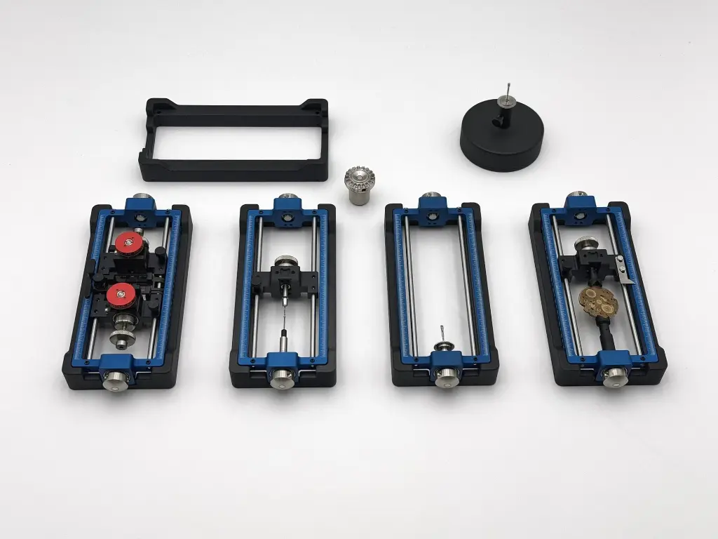
Part Holding Methods
Magnetic positioning
Magnetic or magnetizable parts are positioned using one or more magnetic tips, either by simple contact or combined with partial levitation.
Parts must be positioned so that at least part of the measured surface is in contact with the rotary magnetic section of the fixture.
Rotation from the inspection machine is transmitted to the fixture via a coupling mechanism and thus applied to the part.
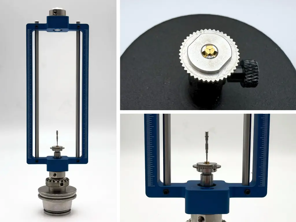
Micro chuck positioning
This allows either direct clamping of the part in the micro chuck, or mounting the part on an intermediate element such as a precision pin, which is then clamped in the chuck.
Ideal for parts with a sufficient clamping surface or a through or blind axial bore.
The VHR micro chuck supports diameters from 0.2 mm to 1.5 mm.
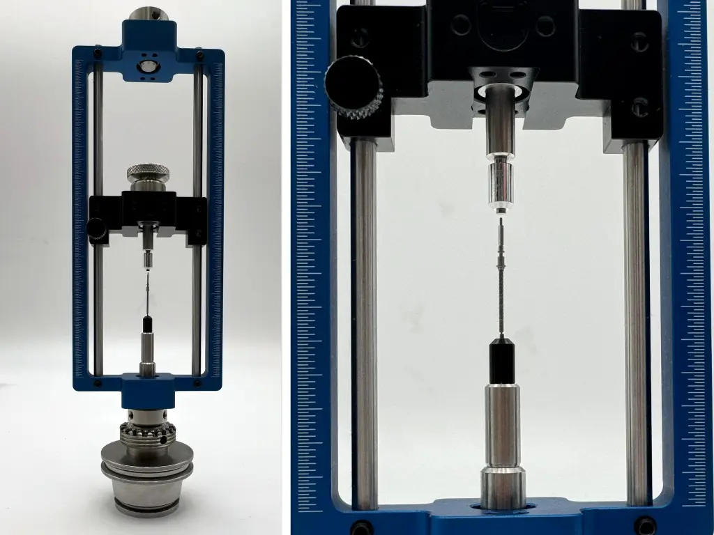
Between-centers positioning
This replicates the classic “between centers” holding method for compatible geometries, in miniature form. Custom tips can be adapted or developed upon request.
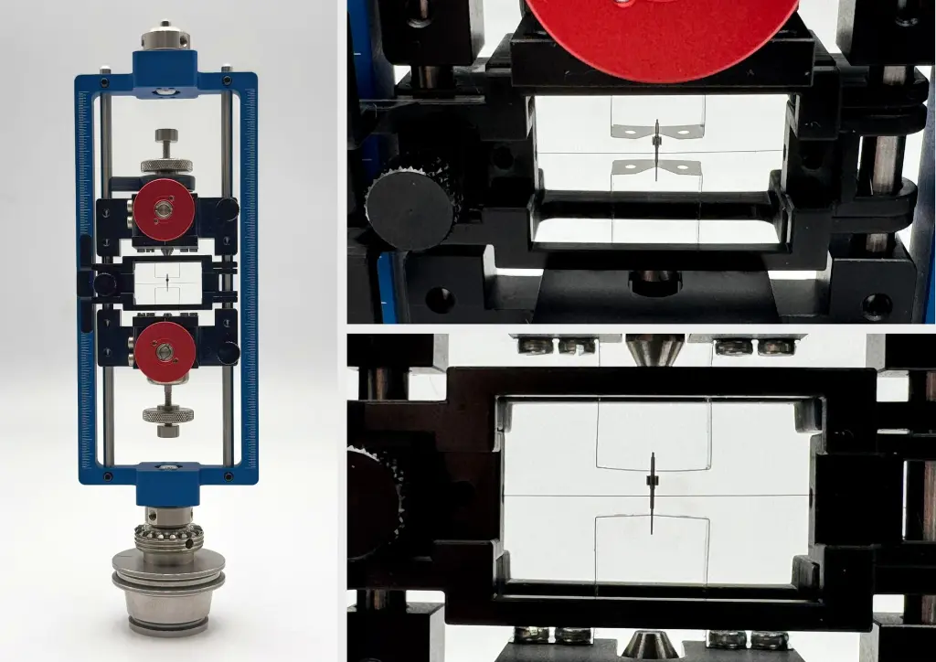
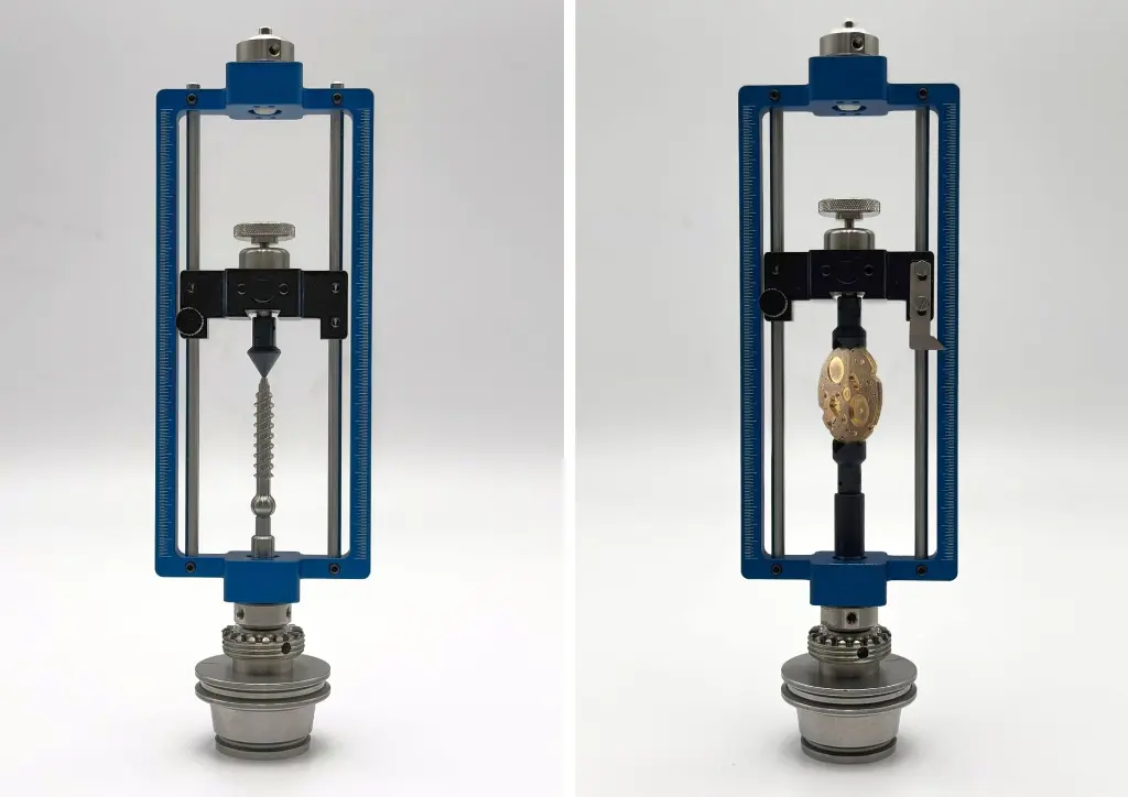
Positioning on fine “V” profile blades
Parts not compatible with previous methods can be held on thin blades (0.05 mm) with a “V” profile and tension wire (0.05 mm).
Parts are first placed on height-adjustable blades to compensate for possible diameter differences at the support points. Centering stops help stabilize placement, and the tension wire is then brought down to secure the part in place.